


Showing posts with label Projects. Show all posts
Showing posts with label Projects. Show all posts
Posted on
Wednesday, 11 April 2012
In this program you give your system coefficents and the Routh-Hurwitz table would be shown
Read More
The Routh-Hurwitz stability criterion is a necessary method to establish the stability of linear time invariant (LTI) control system.
More generally, given a polynomial, some calculations using only the coefficients of that polynomial can lead us to the conclusion that it is not stable. |
In this program you give your system coefficents and the Routh-Hurwitz table would be shown
clc
clear
r=input('input vector of your system coefficents: ');
m=length(r);
n=round(m/2);
q=1;
k=0;
for p = 1:length(r)
    if rem(p,2)==0
        c_even(k)=r(p);
    else
        c_odd(q)=r(p);

        k=k+1;
        q=q+1;
    end
end
a=zeros(m,n);

if m/2 ~= round(m/2)
    c_even(n)=0;
end
a(1,:)=c_odd;
a(2,:)=c_even;
if a(2,1)==0
    a(2,1)=0.01;
end
for i=3:m
    for j=1:n-1
        x=a(i-1,1);
        if x==0
            x=0.01;
        end

        a(i,j)=((a(i-1,1)*a(i-2,j+1))-(a(i-2,1)*a(i-1,j+1)))/x;

    end
    if a(i,:)==0
        order=(m-i+1);
        c=0;
        d=1;
        for j=1:n-1
            a(i,j)=(order-c)*(a(i-1,d));
            d=d+1;
            c=c+2;
        end
    end
    if a(i,1)==0
        a(i,1)=0.01;
    end
end
Right_poles=0;
for i=1:m-1
    if sign(a(i,1))*sign(a(i+1,1))==-1
        Right_poles=Right_poles+1;
    end
end
fprintf('\n Routh-Hurwitz Table:\n')
a
fprintf('\n Number Of Right Poles =%2.0f\n',Right_poles)

reply = input('Do You Need Roots of System? Y/N ', 's');
if reply=='y'||reply=='Y'
    ROOTS=roots(r);
    fprintf('\n Given Polynomials Coefficents Roots :\n')
    ROOTS
else
end
Posted on
Monday, 12 December 2011
Read More
Ever LISTENED to a text message ???

No!!!
Well this project will make you do so.
Surprised ???
Don’t be because AUDIO STEGANOGRAPHY is the
method in which we can encode our secret messages on an audio signal
ensuring their safety. In this way we can decrypt a message on an audio signal
without its detection.
Lsb coding:-
The type of coding used in this project is the LSB
or the Least Significant Coding.
Least significant bit (LSB) coding is the simplest
way to embed information in a digital audio file. By substituting the least
significant bit of each sampling point with a binary message, LSB coding allows
for a large amount of data to be encoded.
Working:-
In this project we first read a wav file using the
MATLAB wavread command. Then we input a message from the user. This
message is then converted into its ASCII coded signal which then bit by bit
replaces the LSB of the wav file. In this way we convert our message into audio
form and transmit it.
At the receiver end when the signal is received or
the audio file is received, we just take out the last bit of the audio signal.
This now is our ASCII coded message we just convert it back into our message
signal.
The program is also generating a graphical user interface, from which you can easily hide the message and can then extract it later. All the related codes as well as the audio files can be downloaded here.
Posted on
Friday, 9 December 2011


The MATLAB code and related files can be downloaded here:-
Audio compression is data compression
designed to reduce the transmission bandwidth requirement of digital audio streams
and the storage size of audio files. Broadly compression techniques are
classified into two types:
- Lossless compression algorithms usually exploit statistical redundancy in such a way as to represent the sender's data more concisely without error. Lossless compression schemes are reversible so that the original data can be reconstructed
- Lossy schemes accept some loss of data in order to achieve higher compression.
In both lossy and lossless compression,
information redundancy is reduced, using methods such as coding, pattern
recognition and linear prediction to reduce the amount of information used to
represent the uncompressed data.
There are numerous methods of compressing
audio files. The Discrete Cosine Transform is a lossy technique that removes
certain frequencies from the audio data such that the size is reduced with
reasonable quality.
The Discrete Cosine Transform is a
first-level approximation to mpeg audio compression, which are more
sophisticated forms of the basic principle used in DCT.
This discrete cosine Transform Audio
Compression is performed in MATLAB.
It takes a wave file as input, compress it
to different levels and assess the output that is each compressed wave file.
The difference in their frequency spectra will be viewed to assess how
different levels of compression affect the audio signals.
PROGRAM WORKING:-
An audio waveform is a continuous sequence of data
in one long vector. In that sense, an audio data structure is different from an
image data structure. We will need to apportion the vector manually into
several pieces, and cannot rely on existing rows or columns.
- Read the audio file
- Determine a value for the number of samples that will undergo a DCT at once. In other words, the audio vector will be divided into pieces of this length.
- Again, we examine at different compression rates:
50%
75%
87.5%
- Resulting compressed-and-uncompressed audio waves
For simplicity, we iterate over the vector,
window-by-window, but we discard whatever remainder exists:
Now we plot
the time domain signals

However, closer inspection does reveal
qualitative differences in the densely packed regions (high frequencies).
A look at the spectrogram reveals a clear
idea of the loss of high frequencies.

The qualitative difference is clearly
apparent when listening to the audio files
- Saving the files and viewing the difference in size
CODE
%read a file and
convert it to a vector
%chosing a block
size
%changing
compression percentages
%initializing
compressed matrice
%actual
compression
%plotting audio
signals
%expanded view of
audio signals
%spectrogram of
audio signals
%playing files
Posted on

Read More
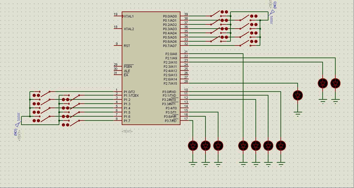
A 3 bit microprocessor can be designed using a 89C51 micro controller. This code for the program is written in the C language. The
code is then loaded into the "Keil uVision 2" Software and a hex file is made
through the software. The Hex File is then burned on to the micro controller
using a micro controller burner. The circuit diagram is shown below and "Proteus"
was used to simulate the software. The Hex file can be directly loaded into the Micro controller using the Proteus Software.
Working of the Project:
Setting numbers as Input:
The project makes use of the basic
programming techniques using the C language. First of all basic programs are
made as functions like addition function, subtraction function, multiplication function
and so on. Then the number is input
through the Port 0 of the micro controller. The input is always a binary
number.
Selecting an Operation:
After the two inputs are set onto
the switches then the operation switch is turned on. Operations are defined on the Port 1 of the micro controller. As it
is a 3 bit microprocessor so the total number of operations would be 23=8.
So the whole Port 1 is for operations. The operations include the basic
mathematical and logical operations. Selection of two operations at the same
time will generate an error and the error bit (Port 2 Pin 7) will turn on
indicating the error.
Displaying an Output:
The output is displayed in
the output registers. As it is a 3 bit microprocessor so all the registers will
be of 3 bits, so when the output of addition is increases than 7 or can’t be
displayed in the three bits the overflow bit (Port 2 Pin 0) is turned on
indicating the overflow.
In case
of multiplication, if the input goes higher than 3 bits then the second
register is used to display the remaining bits of the solution. In this way the
basic architecture of the computer is followed in the microprocessor.
Flag Register:
Flag register is again of
three bits. It contains 3 flag indicators that are zero flag, overflow flag and
the sign flag. The zero flag turns on to indicate a result equal to zero. The
overflow flag turn to indicate the overflow of the 1st output
register. The sign flag indicates a negative result.
Error Bit:
Error
bit is used to indicate an error either in the input port or the operations
port. In case of two operations being turned on at the same time, the error bit
turns on. Similarly when there is division by zero, the error bit indicates the
error.
Note:
This project was implemented and is found fully working. The
hex file and the C file are attached for the help. Furthermore the Proteus design
is also attached along with the files.
Posted on
Thursday, 8 December 2011
Read More
Mixer is a non-linear circuit that combines two signals in such a way to produce the sum and difference of the two input frequencies at the output.


COMPONENTS:-
C1 = 0.1uF
C2 = 0.1uF
C3 = 0.1uF
R1 = R2 = 10kOhm
R3 = R4 = 100kOhm
R5 = 6.8kOhm
The design and simulation was carried out in ADS software. And the circuit is like this:-

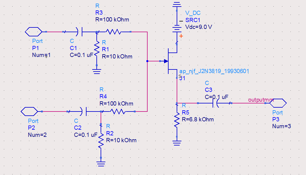
The mixer is implemented by an NPN transistor 2N3904.
The circuit used was basically for audio mixing, it had an input from the triangular wave generator and the noise generator. And it is passsed through the audio mixer to form the wave.
The practical waveform was like dis:-

While the waveform from simulation in ADS was like this:-

Posted on
Monday, 5 December 2011


Read More
The robot project works with two motors for driving the rear
wheels while the front wheels are free.
It uses 4 infra red sensors for detecting the line that it
has to follow. It can be either a black line on white background or a white
line on black background.
AT89C2051 microcontroller is used in the project for instructing the robot to move according to
the sensors input. The motor driving circuit is made with L293D, which is an
H-bridge IC. It can control the two motors simultaneously.
The code is written in C and is a fully functional code.
Care must be taken while choosing the motors. It should be a
high torque motor so that it can take the weight of your robot. Otherwise the
wheels would work fine while in the air but would not move once the robot is
set down.
The sensor circuits as well as the control circuit is given
below and the C code can be downloaded as a word file.
Control circuit:-

Sensors circuit:-
These sensor circuits need to be attatched at the points labeled as sensors in the main figure.

Position of Sensors:-

C code:-
Posted on
Saturday, 3 December 2011
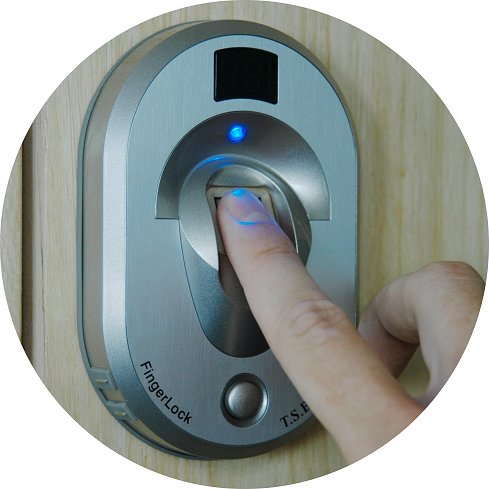
Finger print recognition algorithm is used extensively in security related areas. For accessing any database, authenticating to any special services in your company or any other form of security service that use to ask about your ID cards or stuff like that previously.
Here we have provided the MATLAB code of the Finger Print Recognition Algorithm.
That takes the finger print as an image. The 'add to database' option lets you enrol your fingerprint into the database for future queries.
The 'match option then lets you match the finger print image with the database its going to have.
A user friendly GUI is also developed for this purpose with easily monitored buttons.
The attached file also have some fingerprint images for the testing purpose.
Downloads:
Read More
Finger print recognition algorithm is used extensively in security related areas. For accessing any database, authenticating to any special services in your company or any other form of security service that use to ask about your ID cards or stuff like that previously.
Here we have provided the MATLAB code of the Finger Print Recognition Algorithm.
That takes the finger print as an image. The 'add to database' option lets you enrol your fingerprint into the database for future queries.
The 'match option then lets you match the finger print image with the database its going to have.
A user friendly GUI is also developed for this purpose with easily monitored buttons.
The attached file also have some fingerprint images for the testing purpose.
Downloads:
Posted on

The basic operation of the circuit is based on impedance matching and then amplifying the signal to give it to the output. Two normal speakers can be used both as the input and the output devices. The first stage which is at BC109C receives the signal in the common base configuration. It gives a good voltage gain and low input impedance which is used for impedance matching with the 8ohms speaker.
Self DC bias is used allowing variations in the transistor’s current gain.
The signal is then filtered for any DC part that may be present, through the capacitor. Thus a pure AC audio signal is sent to the 2nd part of the circuit which is the audio amplifier booster.
A constant Vcc is provided to this circuit, the two diodes check the backward flow of current. The signal is amplified on the 2nd stage through 2 transistors in cascade and later the signal is purified through a capacitor and sent to the output speaker. The basic function of the amplifier is to boost the voltage gain of the circuit and than provide it to the output speaker.
The circuit i used instead of LM386 is:-

OUTPUT ANALYSIS
The output analysis of the circuit tells that its providing 2 watts gain to the speaker so that the voice is audible. If the gain of the amplifier exceed s above the limit than the output signal is clipped off.
Read More
The basic operation of the circuit is based on impedance matching and then amplifying the signal to give it to the output. Two normal speakers can be used both as the input and the output devices. The first stage which is at BC109C receives the signal in the common base configuration. It gives a good voltage gain and low input impedance which is used for impedance matching with the 8ohms speaker.
Self DC bias is used allowing variations in the transistor’s current gain.
The signal is then filtered for any DC part that may be present, through the capacitor. Thus a pure AC audio signal is sent to the 2nd part of the circuit which is the audio amplifier booster.
A constant Vcc is provided to this circuit, the two diodes check the backward flow of current. The signal is amplified on the 2nd stage through 2 transistors in cascade and later the signal is purified through a capacitor and sent to the output speaker. The basic function of the amplifier is to boost the voltage gain of the circuit and than provide it to the output speaker.
The circuit i used instead of LM386 is:-

OUTPUT ANALYSIS
The output analysis of the circuit tells that its providing 2 watts gain to the speaker so that the voice is audible. If the gain of the amplifier exceed s above the limit than the output signal is clipped off.
Posted on
Friday, 2 December 2011
Read More
Circuit Diagram:

Components:


Components:
·
2x LM 741 IC’s
·
20kΩ Resistor
·
5kΩ Resistor
·
10kΩ Resistor
·
1.1uF Capacitor
Working:
Assemble the components as shown in the circuit diagram
above. In the above diagram the capacitor C1 acts as a integrator and
integrates the square input into a triangular wave. In this way a triangular
wave is generated.
Results:
Result of the above circuit diagram is a perfect triangular
wave.