A 3 bit microprocessor can be designed using a 89C51 micro controller. This code for the program is written in the C language. The
code is then loaded into the "Keil uVision 2" Software and a hex file is made
through the software. The Hex File is then burned on to the micro controller
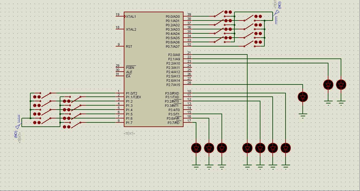
using a micro controller burner. The circuit diagram is shown below and "Proteus"
was used to simulate the software. The Hex file can be directly loaded into the Micro controller using the Proteus Software.
Working of the Project:
Setting numbers as Input:
The project makes use of the basic
programming techniques using the C language. First of all basic programs are
made as functions like addition function, subtraction function, multiplication function
and so on. Then the number is input
through the Port 0 of the micro controller. The input is always a binary
number.
Selecting an Operation:
After the two inputs are set onto
the switches then the operation switch is turned on. Operations are defined on the Port 1 of the micro controller. As it
is a 3 bit microprocessor so the total number of operations would be 23=8.
So the whole Port 1 is for operations. The operations include the basic
mathematical and logical operations. Selection of two operations at the same
time will generate an error and the error bit (Port 2 Pin 7) will turn on
indicating the error.
Displaying an Output:
The output is displayed in
the output registers. As it is a 3 bit microprocessor so all the registers will
be of 3 bits, so when the output of addition is increases than 7 or can’t be
displayed in the three bits the overflow bit (Port 2 Pin 0) is turned on
indicating the overflow.
In case
of multiplication, if the input goes higher than 3 bits then the second
register is used to display the remaining bits of the solution. In this way the
basic architecture of the computer is followed in the microprocessor.
Flag Register:
Flag register is again of
three bits. It contains 3 flag indicators that are zero flag, overflow flag and
the sign flag. The zero flag turns on to indicate a result equal to zero. The
overflow flag turn to indicate the overflow of the 1st output
register. The sign flag indicates a negative result.
Error Bit:
Error
bit is used to indicate an error either in the input port or the operations
port. In case of two operations being turned on at the same time, the error bit
turns on. Similarly when there is division by zero, the error bit indicates the
error.
Note:
This project was implemented and is found fully working. The
hex file and the C file are attached for the help. Furthermore the Proteus design
is also attached along with the files.